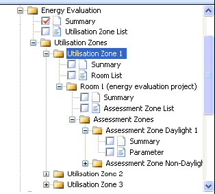
There are several outputs for an energy evaluation, to show the calculated energy demands for different objects.
The calculated total energy demands for lighting and other energetic characteristics can be shown for the complete energy evaluation project, for each contained utilization zone, each energy evaluation room and for each assessment zone. A subdivision in monthly values is also possible for each object.
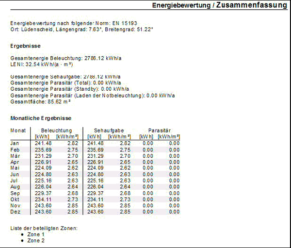
Fig. 436 Output for the complete energy evaluation project with all important characteristics
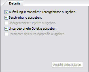
Of course, the user has the possibility to select which details are shown on each output page.
Fig. 437 Property page of the above output page
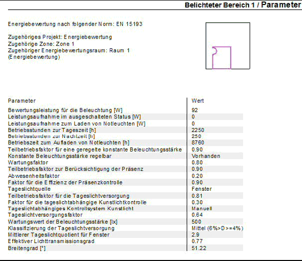
The output of all involved parameters is most important, because all energy performance standards demand such documentations.
Fig. 438 Parameter output for an assessment zone
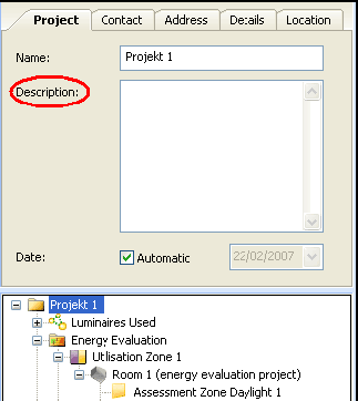
Attention should be paid to the possibility of using descriptions for assessment zones and other energy evaluation objects. These descriptions should not be too long, but should frequently be used.
With short, precise comments you can explain the selection of one or more parameter. Particularly with regard to manually adjustments to automatically calculated values such explanations are in fact mandatory.
Fig. 439 Input of a description for an assessment zon
STF Interface
The STF interface is supported by DIALux since version 1.0. The interface is continuously extended and improved. Via STF CAD programs can exchange their planning data with DIALux. The workflow is normally as follows:
Design in the CAD application by the architect / engineer.
Design of the building, the storey or the room(s). If necessary the luminaire positions can be defined in the CAD application as well, for example in the case of a redevelopment or if the luminaires have to be placed in certain positions.
Export of the information via STF file to DIALux.
Import of the STF file into DIALux. All the rooms defined in the CAD will appear in the DIALux project, including additional information like the position of doors, windows, degree of reflection, room information…. The user can now do the lighting design in DIALux. The correct fittings can be placed; additional calculation objects can be defined. The calculation will be done and the documentation of the design can be made in DIALux.
Export of the revised STF file from DIALux to the CAD application.
Depending on the CAD software used, a different level of information from the DIALux STF file is read in. The information exported by DIALux is for example the luminaire name, article number, description, electrical and light technical parameter, pictures, 3D model, isoline diagram and so on.
Further information about the STF interface can be obtained from dialog@dial.de or hotline@dialux.com