- Главная
-
Учебник
- DIALux 4
- DIALux evo
- IES
- Форум
- Галерея
- Блоги
-
Скачать
- DIALux
- Базы
- Плагины
- 3D модели
- Текстуры
- Книги
-
Новости
Camera
11 сентября 2012 - АдминThe camera definition describes the position, projection type and properties of the camera viewing the scene. Interesting types are spherical, cylinder and panoramic. In the POV-Ray help a number of camera types are explained. If none is specified, the perspective camera is the default. The perspective keyword specifies the default perspective camera which simulates the classic pinhole camera. The (horizontal) viewing angle is either determined by the ratio between the length of the direction vector and the length of the right vector or by the optional keyword angle, which is the preferred way. The viewing angle has to be larger than 0 degrees and smaller than 180 degrees. In the “camera” area of the POV file the settings for the camera can be changed.
camera
{
location CAMLOCATION // parameter for the position, is defined in the beginning of the file
right <16/9,0,0> // right vector of the
camera
up <0,1,0> // up vector of the camera
sky <0,1,0> // Vector for the sky
angle 77 // viewing angle
look_at CAMLOOKAT // viewing direction of the camera
}
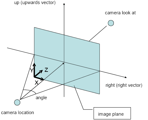
The primary purpose of the up and right vectors is to tell POV-Ray the relative height and width of the view screen. In the default perspective camera, these two vectors also define the initial plane of the view screen before moving it with the look_at or rotate vectors. The length of the right vector (together with the direction vector) may also be used to control the (horizontal) field of view with some types of projection. The look_at modifier changes both the up and right vectors. The angle calculation depends on the right vector.

Fig. 461 Camera look and location
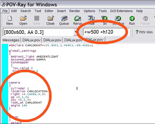
This picture shows the definition of the field of view. The blue plane is the image plane. DIALux exports those values as they are defined in the 3D view of the CAD. Depending on the camera type used, those values can differ. See POV-Ray help for more details. To create a “round view” the camera type “cylinder” is useful. Especially in exterior scenes interesting views can be created. To define such a view the user has to enter the command “cylinder 1” in the area of camera. Use 180° for the angle. It is important to select a correct image size. If you want to have a picture of 500 to 120 the picture ratio has to be 4.2666. The following image is calculated with a 180 degree viewing angle and a cylindrical camera.

Fig. 462 Exterior scene visualisation

Fig. 463 Settings camera locationРейтинг: 0 Голосов: 0 6590 просмотровКомментарии (0)Manual
